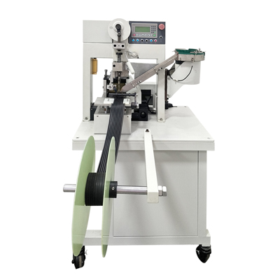
An Automatic Riveting Machine is an industrial device designed to join materials (typically metals or plastics) through the automated insertion and deformation of rivets. These machines combine precision engineering with programmable logic controllers (PLCs) to achieve high-speed, consistent riveting operations. Modern models feature servo-electric or pneumatic actuation systems with positioning accuracy of ±0.02mm and cycle times as fast as 0.8 seconds per rivet. Force monitoring capabilities typically range from 50N to 50kN (depending on application), with advanced models incorporating real-time quality assurance through load-displacement curve analysis.

Key Technical Specifications:
Positioning Accuracy: ±0.01-0.05mm (servo-driven models)
Cycle Time: 0.5-3 seconds per rivet (model dependent)
Force Capacity: 100N to 100kN (with 1% measurement accuracy)
Tooling Options: Radial, orbital, or impact riveting configurations
Control Systems: PLC with HMI interfaces, often with IoT connectivity
Primary Applications
Automatic Riveting Machines serve critical functions across multiple industries:
1. Automotive Manufacturing
In vehicle assembly lines, these machines achieve 300-500 rivets per hour when joining aluminum body panels (0.8-2.0mm thickness) with 4-6mm diameter rivets. The aerospace-grade models process titanium rivets (3-8mm) at 180-240 rivets/hour for chassis components.
2. Electronics Assembly
Precision micro-riveting systems handle 0.5-3mm rivets in smartphone casings (aluminum 6063 alloys) with 0.02mm repeatability, operating at 1.2 second cycles for 5G antenna module assemblies.
3. Aerospace Components
CNC-controlled riveters process 10,000+ rivets per aircraft fuselage (typically 4-10mm diameter), with force monitoring to ±2% of setpoint for critical structural joints in wing assemblies.
4. Appliance Manufacturing
High-volume production lines for washing machine drums utilize multi-head riveters placing 6-12 rivets simultaneously (stainless steel 1.5-3.0mm) at 15-20 second cycle times per unit.
Maintenance Procedures
Daily Maintenance
Lubrication: Apply ISO VG 32 hydraulic oil to pneumatic cylinders (2 drops per port) and NLGI #2 grease to guide rails (5g per linear meter)
Cleaning: Remove metal particulates from tooling areas using compressed air at ≤0.7MPa pressure
Inspection: Verify C-frame alignment within 0.05mm/meter using dial indicators
Weekly Maintenance
Force Calibration: Verify load cell accuracy using reference weights (typically ±1% of full scale)
Pneumatic System: Drain moisture from filters and check air pressure stability (maintain 0.5-0.7MPa)
Electrical Checks: Measure servo motor current draw (should not exceed nameplate rating by >10%)
Quarterly Maintenance
Bearing Replacement: Change guide rail bearings after 500,000 cycles (or when radial play exceeds 0.01mm)
Hydraulic System: Replace hydraulic fluid (ISO VG 46) after 2,000 operating hours
Tooling Inspection: Measure rivet set wear using go/no-go gauges (replace at >0.1mm diameter change)
Annual Overhaul
Structural Inspection: Check frame for stress cracks using magnetic particle testing (MT) or dye penetrant (PT)
Control System: Update PLC firmware and backup parameters
Accuracy Verification: Perform ballbar testing on CNC axes (compensate if error >0.03mm)
Critical Replacement Intervals:
Pneumatic seals: 1 million cycles
Servo motor brushes: 10,000 operating hours
Hydraulic hoses: 5 years (regardless of visible wear)
Tooling inserts: 50,000-200,000 cycles (material dependent)


